Ripple Radios
2,371 supporters
Anmelden
Anmelden
Ripple Radios
Beiträge
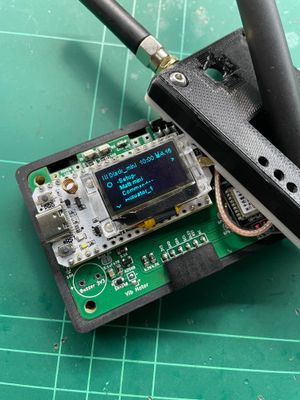
Build Guide: QWERTY Pager for StickLite
...
Build Guide: QWERTY Pager for StickLite V2
Sep 16, 2023
1 like
Teilen
Gefällt dir dieser Beitrag?
Kaufe Ripple Radios einen Kaffee
Unterstützen
1 like
Teilen
Mehr von Ripple Radios
Item 1 of 1
Deutsch
English
Deutsch
Español
Italiano
Français
Українська
Datenschutz
Nutzungsbedingungen
Melden
Starte deine „Kauf mir einen Kaffee“-Seite